Search News
TerraVista Metrics (TVM)Industry Portal
TerraVista Metrics (TVM)Hot Articles
TerraVista Metrics (TVM)- What Drives System Interoperability Testing Service Costs in Complex Projects?System interoperability testing service cost depends on integration scope, workflows, environments, and assurance needs. Learn how to budget smarter and reduce project risk.
- Project Planning Sourcing Guides: How to Qualify Suppliers Before Work StartsSourcing guides project planning helps teams qualify suppliers before work begins—verify compliance, delivery capacity, financial strength, and sustainability to reduce risk and protect project outcomes.
- Buyer’s Guide to Kinetic Art: Choosing Safe, Durable Pieces for Public SpacesBuyer guides kinetic art for public spaces: learn how to choose safe, durable, low-maintenance installations with reliable engineering, materials, controls, and lifecycle value.
Popular Tags
TerraVista Metrics (TVM)Industry NewsIndustrial Compressors: How to Size Air Capacity and Pressure for Factory Demand
auth.Julian Thorne (Sustainable Infrastructure Architect)Time
Oct 06, 2026Click Count
Start with the Air Demand Profile, Not the Compressor Nameplate
Correctly sizing industrial compressors begins with a distinction that is often lost in early equipment discussions: a factory does not require a compressor rated at the sum of every pneumatic device’s maximum catalog consumption. It requires a compressed-air system that can deliver the required flow at the required pressure, with acceptable stability, air quality, energy use, and contingency under the plant’s real operating pattern.
A compressor selected only by installed motor power or nominal free air delivery can be oversized, undersized, or mismatched to the control pattern. An oversized fixed-speed unit may spend much of its operating time unloaded, wasting electricity and increasing wear. An undersized unit may maintain production only by raising discharge pressure, running continuously at full load, or relying on a second machine with inadequate reserve capacity. Neither condition is a sound basis for technical approval.
The starting point is a demand profile expressed as free air delivery (FAD), normally in m³/min, m³/h, L/s, or scfm, at defined reference conditions. This should be matched to the plant’s pressure requirement at the point of use, not merely to the compressor discharge pressure.
Calculate Required Flow from Connected Loads and Measured Consumption
Where a facility is new or has no reliable metering history, connected equipment provides the initial estimate. Each air-consuming device should be recorded with its rated air consumption, operating pressure, duty cycle, simultaneity, and operating mode. The relevant users include not only production machines but also blow guns, dust removal systems, valve manifolds, air motors, pneumatic conveying equipment, packaging systems, instrument air, and maintenance connections.
A preliminary demand estimate can be expressed as:
Required FAD = Σ (device air consumption × duty factor × simultaneity factor) + leakage allowance + contingency
The formula is simple; applying it correctly is not. A pneumatic cylinder may consume air only during a short actuation cycle. A bagging line may draw heavily during a specific sequence rather than continuously. Several machines may be installed on the same line but never operate together. Conversely, a plant may have synchronized equipment that creates a sharp, repeated demand peak that a simple average calculation fails to reveal.
Duty factor represents the proportion of time a device consumes air during the defined period. Simultaneity represents the share of similar loads expected to operate at once. These factors should be based on the operating schedule and control logic rather than generic assumptions. Applying a blanket diversity factor to all equipment can conceal a genuine peak load, particularly on automated lines where multiple pneumatic functions are triggered together.
For an operating factory, flow measurement is more valuable than an inventory-based calculation. Install a properly sized flow meter at the main header or, preferably, at meaningful zones such as production lines, utility users, and high-demand processes. Logging should capture enough resolution to identify short peaks, startup events, shift changes, and idle periods. One-minute averages may be adequate for broad load assessment, but fast-cycling processes may require shorter intervals to reveal pressure instability and receiver requirements.
A useful load study records at least:
- average flow during normal production;
- maximum sustained flow over a realistic operating interval;
- short-duration peak flow and its frequency;
- minimum demand during breaks, night operation, or standby;
- flow during non-production periods, which is often a leakage indicator;
- main header pressure and pressure at critical end-use points.
The highest instantaneous meter value should not automatically become the compressor capacity target. A brief peak may be better handled by stored air in a correctly sized receiver, provided that the pressure band remains acceptable. The decisive question is how much air is required, for how long, and how much pressure variation the process can tolerate.
Separate Base Load, Variable Load, and Short Peaks
Industrial compressed-air demand is rarely flat. A more reliable sizing basis divides demand into three functional components.
Base load is the relatively stable demand that persists through normal production. It may include continuous air knives, instrument air, purge flows, and machines operating for most of a shift. This portion is often a good fit for a fixed-speed compressor if the load remains sufficiently high and stable.
Variable load changes with production rate, product mix, shift pattern, or the number of lines in service. Variable-speed drive compressors can be effective when demand changes materially across the operating period, but their suitability depends on actual turndown range, control stability, minimum speed behavior, and the presence of other compressors in the system.
Short peaks occur when high-flow actions overlap: a pneumatic conveying cycle, a mold blow-off sequence, simultaneous actuator movement, or a plant-wide restart after a power interruption. Sizing the main compressor to every short peak may create excessive unloaded capacity. A receiver located near the high-demand process, combined with suitable piping and pressure controls, can often support these events more efficiently.
This distinction also informs multi-compressor sequencing. A system with one large compressor may appear economical on a capacity sheet, but it has limited flexibility when demand falls substantially below its rated output or when the unit is unavailable. Multiple compressors, selected and controlled around the actual load profile, can provide better part-load performance and maintenance resilience. The configuration should not be selected simply because “N+1” capacity is requested. Reserve capacity must be defined against the consequences of losing a unit, the production loads that must remain active, and the time required to restart or repair equipment.
Leakage Is a Load, Not a Generic Percentage
Leakage allowance is necessary, but an arbitrary percentage is a weak engineering input. Leaks vary widely with system condition, pressure, maintenance discipline, and the number of temporary or poorly managed connections. A facility with a known leakage problem should not normalize the loss by purchasing larger industrial compressors. That approach treats wasted air as permanent production demand and increases the energy cost of the entire system.
The most direct field estimate is a no-production test. When legitimate air users are isolated or inactive, the air consumed to maintain pressure represents leakage plus any intentional continuous loads that remain connected. With an adequately sized receiver and stable conditions, leakage can be estimated from the rate of pressure decay:
Leakage flow ≈ Receiver volume × pressure drop / elapsed time
The calculation must use absolute pressure and consistent units. It also requires confidence that there is no active process consumption, temperature-driven pressure change, or uncontrolled connection to another section of the plant. In many cases, a flow meter during a verified shutdown period provides a clearer answer.
Leakage should be reported separately from productive demand. This preserves decision visibility: the compressor may need to cover current losses temporarily, but the system specification should identify the flow that can be recovered through repair. Pressure reduction also matters. A leak at a higher pressure passes more air, and raising system pressure to compensate for poor distribution can compound the loss.
Set Pressure at the End Use, Then Work Back Through the System
Pressure sizing should begin with the device that has the most demanding legitimate requirement. The relevant value is the minimum pressure needed at that point of use while the process is operating. It is not necessarily the highest pressure printed on an actuator datasheet, and it is not automatically the setting required at the compressor.
The compressor discharge pressure must cover the minimum point-of-use requirement plus all pressure losses between the compressor and the critical user:
Required compressor discharge pressure = critical end-use pressure + distribution loss + treatment loss + control margin
Distribution loss includes pipe friction, undersized headers, long branch runs, excessive fittings, restrictive quick couplings, partially closed isolation valves, and high-velocity sections. Treatment loss includes air dryers, filters, separators, adsorption towers, and any downstream purification equipment. Control margin allows for normal cycling and the difference between load and unload pressure settings or variable-speed control band.
Pressure drop must be assessed at peak flow, not only at normal flow. Losses in piping and filters rise as flow increases. A system that appears acceptable during average operation may starve a critical machine when multiple loads operate together. Pressure should therefore be logged at both the compressor room header and the critical point of use during representative production conditions.
Many systems are operated at unnecessarily high pressure because the true restriction has never been isolated. If a machine needs 6.0 bar at its inlet but receives only 5.5 bar during a peak event, increasing compressor setpoint to 8.0 bar may restore operation while masking an undersized filter, a poor regulator, or a restrictive branch line. The more durable solution is to identify where the pressure is being lost. Higher pressure increases compressor energy demand and can worsen leakage, artificial demand, and wear on pneumatic components.
Do Not Confuse Gauge Pressure, Absolute Pressure, and Compressor Test Conditions
Pressure data in plant discussions are normally gauge values: bar(g), psig, or kPa(g). Thermodynamic calculations and certain flow conversions require absolute pressure: bar(a), psia, or kPa(a). One barometric atmosphere must be added when converting a gauge pressure to absolute pressure. Confusing the two produces substantial errors in receiver sizing, compressed-air storage calculations, and conversion between actual volumetric flow and free air delivery.
Flow ratings require the same care. Compressor catalog values may be stated as FAD under a defined standard condition, while a local flow meter may report actual volume at line pressure or standardized volume at a different reference temperature and pressure. Before comparing a measured plant load with a supplier’s performance curve, confirm:
- the reference temperature and absolute pressure used for the stated flow;
- whether humidity is included in the reference condition;
- the specified discharge pressure at which FAD is guaranteed;
- whether quoted output is package-level performance or air-end displacement;
- the tolerance, measurement method, and applicable test standard stated by the supplier.
Air-end displacement is not the same as delivered air. Internal losses, inlet conditions, discharge pressure, and control state affect actual usable output. Technical comparisons should be made using delivered FAD at the required working pressure, not using nominal swept volume or motor rating as a proxy for capacity.
Receiver Volume Determines How the System Absorbs Demand Events
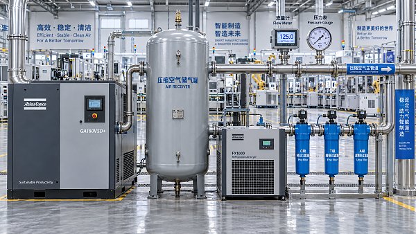
An air receiver is often treated as an accessory, but it is part of capacity management. It stores compressed air, smooths pulsation, reduces rapid compressor cycling, and supplies short-duration demand that may exceed compressor output. Its effectiveness depends on usable pressure swing.
For a defined peak event, receiver sizing can be estimated from the air deficit:
Receiver volume = Air deficit × event duration × atmospheric pressure / usable absolute pressure drop
The air deficit is the peak process demand minus compressor output during that event. The usable pressure drop is the difference between maximum and minimum allowable receiver pressure, expressed in absolute terms. If a process cannot tolerate more than a narrow pressure change, a large receiver may be required; alternatively, the distribution arrangement or compressor control strategy may need revision.
Receiver placement is equally important. A wet receiver near the compressor supports general system stability and condensate separation. A dry receiver downstream of the dryer supports clean, dry storage and may be preferable where downstream pressure stability is critical. Local storage close to intermittent high-demand equipment can prevent a brief event from causing a plant-wide pressure dip. This arrangement is particularly useful when the main header has adequate average capacity but insufficient transient response.
Air Treatment Changes Both Flow and Pressure Requirements
Dryers and filters should be included in the same calculation rather than appended after compressor selection. A refrigerant dryer, desiccant dryer, coalescing filter train, sterile filtration system, or carbon adsorption stage introduces pressure loss that varies with flow and maintenance condition. Filters become more restrictive as elements load with contaminants. Their initial clean pressure drop is not the only value that matters.
Air quality requirements should be defined by the process before selecting treatment equipment. ISO 8573-1 is widely used to specify compressed-air purity classes for particles, water, and oil, but a purity class alone does not select the equipment. The operating environment, inlet air condition, compressor lubricant arrangement, dew point requirement, flow range, and consequences of contamination all affect the treatment design.
Dryer capacity must also be evaluated under actual inlet conditions. A rated flow at one inlet temperature, pressure, and ambient condition may not represent capacity under hotter compressor discharge air or lower operating pressure. Pressure drop and regeneration air consumption, where applicable, belong in the overall air balance.
Allow for Expansion Without Designing Around Uncertain Demand
Future expansion should be accommodated through a defined planning basis, not an undefined safety factor. If a new line has an approved air-consumption schedule, its expected load can be included. If expansion is speculative, installing modular capacity or reserving space, electrical infrastructure, and header connections may be more rational than permanently operating an oversized compressor at poor part-load efficiency.
The same principle applies to redundancy. A required backup machine should be capable of supporting the loads that must continue during a failure, not necessarily every non-critical air use. Categorizing loads as essential, production-critical, deferrable, and non-essential makes this decision measurable. It also enables load-shedding logic during abnormal conditions rather than forcing the compressed-air plant to carry an uneconomic reserve at all times.
A Defensible Compressor Specification Is a System Specification
A robust technical specification for industrial compressors states more than a nominal flow and pressure. It defines required FAD at the stated discharge pressure; demand profile and peak duration; ambient and inlet conditions; pressure at critical end uses; acceptable system pressure band; air-quality requirements; treatment pressure losses; receiver arrangement; control philosophy; electrical constraints; and required availability during maintenance or failure.
The central sizing decision is therefore not “Which compressor is large enough?” It is whether the proposed system can supply the measured or calculated air mass required by the factory, at the lowest stable pressure that the process genuinely needs, across normal operation, peak events, and credible future conditions. When capacity, pressure loss, storage, leakage, and controls are evaluated together, compressor selection becomes an engineering decision rather than a nameplate comparison.
Recommended News
 Sep 22, 2026Industrial Compressors: How to Size Air Capacity and Pressure for Factory DemandIndustrial compressors sizing guide: calculate factory air capacity, end-use pressure, peak demand, receiver storage, leakage, and energy-efficient system performance.
 Sep 09, 2026Sustainable Building Materials Pricing: How Buyers Compare Cost, Life Cycle, and RiskSustainable building materials pricing explained: compare installed cost, life-cycle value, carbon evidence, and supply-chain risk for smarter procurement decisions.
 Aug 29, 2026How to Assess Modular Building Suitability for Middle East Climate and Site ConditionsModular building assessment Middle East: evaluate heat, dust, corrosion, logistics, compliance, and lifecycle value for resilient site-ready projects.
 Aug 16, 2026EU Sets Mandatory Carbon Footprint Certification for Imported Modular CabinsEU mandatory carbon footprint certification will reshape imported modular cabins compliance from 2027. Learn key EU rules, EN 15804+A2 impacts, exporter risks, and how to prepare early.
 Aug 12, 2026New Exit Compliance Rule Reshapes Bids and AI Travel ProofExit compliance rule now reshapes bids and AI travel proof, raising export compliance demands for glamping tents, modular cabins, smart lighting, and kiosk tech. Learn what changes first.
 Jul 13, 2026EU Fire Rule Tightens Testing for Modular CabinsEU Fire Rule Tightens Testing for Modular Cabins: learn how EN 13501-1:2026 shifts CE compliance to component fire testing, impacts lead times, and affects EU export planning.
 Jul 12, 2026Prefab Thermal Efficiency Analysis: Which Metrics Matter for Off-Grid Cabin Design?Prefab thermal efficiency analysis for off-grid cabins: discover the key metrics that shape energy use, comfort, moisture control, and smarter supplier selection.
 Jul 11, 2026EN 16893:2026 Takes Effect for Modular CabinsEN 16893:2026 takes effect for modular cabins in the EU, making third-party verification essential for customs, listing, and project approval. Learn the key compliance changes now.
 Jul 10, 2026China Customs Tightens EU Modular Cabin DeclarationsChina Customs tightens EU Modular Cabin declarations: learn the new EN 16893:2026 and CNAS filing rules, 72-hour delay risks, and how exporters can stay compliant.
 Jul 09, 2026Berlin ITMA 2026 Adds Modular Cabins ZoneBerlin ITMA 2026 adds a Modular Cabins Zone for carbon-neutral prefab solutions, featuring verification, compatibility testing, and cross-border sourcing insights. See what buyers and suppliers should watch.
 Jul 09, 2026Modular Tourism Structures Cost: 7 Factors That Affect Budget, Transport, and InstallationModular tourism structures cost explained: discover the 7 key factors shaping budget, transport, and installation, and learn how to avoid hidden expenses before signing.
 Jul 07, 2026Vietnam Enforces New Import Rules for Modular CabinsVietnam Enforces New Import Rules for Modular Cabins: learn how VNSP registration, QR labeling, and LCA carbon filings affect customs clearance, supplier readiness, and delivery risk.
![]() Jul 06, 2026Vietnam Mandates QR Traceability Labels for Modular CabinsVietnam mandates QR traceability labels for Modular Cabins from July 15, 2026. Learn the new compliance rules, port return risks, and key actions for exporters and buyers.
 Jul 05, 2026Pre-Engineered Cabins Buying Guide: Key Specs, Layout Options, and Cost FactorsPre-engineered cabins buying guide covering key specs, layout options, and real cost factors. Learn how to compare suppliers, avoid hidden costs, and choose units built for long-term performance.
 Jul 04, 2026How to Choose Insulated Hospitality Units for Year-Round Resorts and Remote SitesInsulated hospitality units for year-round resorts and remote sites: learn how to compare thermal performance, durability, compliance, and lifecycle cost for smarter investment decisions.
 Jul 01, 2026EN 13501-1:2026 Takes Effect for Modular CabinsEN 13501-1:2026 now reshapes market access for Modular Cabins. Learn how B-s1,d0 ratings, third-party testing, and CE/UKCA marking affect exports, customs, and delivery planning.
 Jun 30, 2026Djibouti Port Adds Dual Checks for Modular CabinsDjibouti Port adds dual checks for Modular Cabins: thermal imaging and advance EPD filing. Learn how the 3.7-day pre-clearance rule impacts Red Sea shipping, escort priority, and delivery planning.
 Jun 29, 2026EU Fire Rule Tightens for Modular Cabin ExportsModular Cabins exporters face a major EU compliance shift: EN 13501-1:2026 now ties CE marking to mandatory SBI fire testing. Learn the risks, deadlines, and actions needed for EU market access.
 Jun 27, 2026EU EN 16435:2026 Takes Effect for Modular CabinsEU EN 16435:2026 takes effect for Modular Cabins on July 1, 2026, adding Rf 60 and Sd2 tests. Learn how the new CE compliance rules impact certification, testing timelines, and EU shipments.
 Jun 27, 2026Prefab Hospitality Testing and Code Compliance: What to Check Before Project ApprovalPrefab hospitality testing code compliance starts with the right checks. Learn what to verify in structure, fire, MEP, accessibility, and documentation before project approval.
 Jun 26, 2026Red Sea Disruption Extends Modular Cabin Lead TimesRed Sea disruption extends Modular Cabin lead times as Asia-Europe shipping costs rise and 40HQ transit reaches 42 days. See how exporters and buyers can reduce delivery risk now.
 Jun 24, 2026Riyadh Modular Housing Tenders AccelerateRiyadh modular housing tenders accelerate as 27 projects seek SASO 2201:2025-compliant prefabricated units. Explore the 32,000 modular cabins opportunity and 180-day delivery challenge.
 Jun 23, 2026Hormuz Reopening May Cut Camp Export Freight Costs 12%Hormuz reopening may cut camp export freight costs 12%, helping Modular Cabins and Glamping Tents shipments to Saudi Arabia, the UAE, and Qatar. See what exporters should adjust now.
 Jun 22, 2026CBAM Reporting Extends to PV Mounts From JulyCBAM Reporting Extends to PV Mounts From July, making batch-level carbon reporting a critical export requirement. Learn how PV mounts suppliers can protect EU and U.S. project access.
Quarterly Executive Summaries Delivered Directly.
Join 50,000+ industry leaders who receive our proprietary market analysis and policy outlooks before they hit the public library.